Here we provide a practical protocol for building a confocal microscope using off-of-shelf optical components from Thorlabs’ catalog, one of the major optical
manufacturers. The design and evaluation have been implemented using Zemax OpticStudio, the standard optical system design software. In our design, we have two
main changes to Figure 1. The first one is the replacement of the dichroic mirror by a beam splitter. Dichoric mirrors reflect and transmit light at two different
wavelengths (e.g., color). For example, a longpass dichroic mirror with a cutoff wavelength of 490 nm reflect light with wavelength shorter than 480 nm towards
the microscope objective lens in the illumination system and transmit wavelength larger than 500 nm towards the tube lens in the detection system. Conversely,
beam splitters are optical elements that split incident light into two beams regardless of the wavelength. Although a beam splitter is not the desired optical
element to build an experimental confocal microscope due to the loss of energy, it allows us to analyze the performance of the confocal microscope at different
wavelengths without replacing the dichroic mirror. The second change is replacing the microscope objective lens with a condenser lens for design simplicity.
Let us start building a confocal microscope. The Zemax design of the microscope objective lens and tube les are found on Thorlabs’ website. The first element of
the confocal microscope to insert is the beam splitter (Surface 2 in Fig. 2), which reflects the incident beam down at a 90o angle. Remember that the beam splitter
separates the incident beam in two directions: one beam is transmitted through the beam splitter, and the second is reflected as a mirror does. The beam splitter
was created by inserting a foldable mirror surface after the first element (a dumb surface, Surface 1 in Fig. 2) in our system with an angle of 45o.
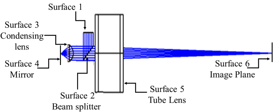
[Fig.2. Two-dimensional optical layout of the confocal microscope in Zemax OpticStudio.]
The second element in our system is an aspheric condenser lens (Surface 3 in Fig. 2), which replaces the microscope objective lens. Without any loss of generality,
we select the AC1210U-A Thorlab’s aspheric condenser lens with a diameter of 12 mm, a focal length of 10.5 mm, and a numerical aperture (NA) of 0.54. The AC1210U-A
lens has a focal spot size equal to 3.953 µm at a wavelength of 633 nm.
The third element of the confocal microscope is a flat mirror. This mirror mimics a perfect thin fluorescent sample, reflecting the light back into the condenser
lens. Since the confocal microscope is a point-based illumination, the mirror should be located at the focal plane of the condensing lens. Based on the
manufacturer’s datasheet, the focal plane is placed at a distance equal to 6.725 mm distance from the last surface of the lens.
The diverging light reflected by the mirror is collimated by the condenser lens, generating a collimated plane wave after the condenser lens. A collimated plane
wave is such a wave whose size does not change, generating a point source at infinity. The collimated plane wave meets the tube lens (TTL200-A, Thorlabs), which
is Surface 5 in Fig. 2. The separation between the condenser lens and the tube lens is irrelevant since the wave is collimated. Nonetheless, we ensure that the
distance was enough so that the tube lens is after the beam splitter in Fig. 2. Since the tube lens is illuminated by a collimated plane wave, focusing the light
into a point at its image plane. Based on the manufacturer’s datasheet, the image plane is located at 152.008 mm to the last surface of the tube lens. In an actual
experiment, the image plane is the plane to set the pinhole. It is important to mention that the tube lens is shown as a black box in Fig. 2. We have chosen
this lens to optimize the performance of the confocal microscope. This type of tube lens is known for its careful design, which contains multiple optical
surfaces to compensate the optical aberrations further.